A Glimpse Inside
the Speedchimp Racing Aerodynamics Laboratory
Part 1 – The Idea
& The Concept
24 Hours or LeMons entries can roughly be lumped into four
types of cars/teams:
Type 1 – Teams that show up with and race a complete pile of
crap that should have been left in the wrecking yard (probably the most
prevalent type of entry).
Type 2 – Teams that show up with a really, really good theme
including costumes and either an over-the-top art car, or a really good parody
of a real race car (a replica of the Oscar Meyer wienermobile or a car with a
20’ blimp attached to the roof).
Type 3 – Teams that show up with a heavily modified
monstrosity of car (a Miata with a working moonshine still or a car powered by
a 90 year old airplane motor).
Type 4 – Teams that show up with a car that is completely
unsuitable for racing (a stretch Limousine for example).
Getting accepted to a race is very dependant on the 24 Hours
of LeMons judges being intrigued by your entry and we
at Speedchimp Racing had a minor problem.
Even though our car really is a 30+ year old piece of crap, it didn’t really look that bad. When we started working on it, we began
finding some serious problems, but many people who saw the car were surprised
that we weren’t going to just fix it up and sell it for a profit. Something else we learned after purchasing
the car is that the LeMons community considers Mazda RX-7s to be a little bit
on the “cheaty” side (An opinion that is completely unfounded in my opinion). For instance, the 1st Generation
RX7 utilizes a live rear axle (which can also be found on pickup trucks, Ford
Mustangs, mini-vans, and other vehicles known for superior handling)
incorporating a Watts Linkage; the cutting edge of 18th century steam
engine technology.
We weren’t a Type 1 team because our car was too nice. We weren’t a Type 3 team because frankly, we
don’t have the tools or skills to make those kinds of modifications. And we weren’t a Type 4 team because regardless
of antiquated mechanical design, the RX-7 is still considered a sports car with
an actual history of winning races.
That left us as a Type 2 team and presented a new
problem. With the exception of Melissa,
none of us are really what you would consider to be “dress up” people. Costumes?
Ugh… That story can be covered in another chapter. I’m going to
concentrate on the transformation of our worn out RX7 into a fast looking race
car.
During the whole creative process for developing our car and
theme, we really wanted to stay away from ideas that had already been to
death. Pretty early on we decided that
we should pretend our car was something that it very obviously was not, but we
didn’t know exactly what. We had some
ideas, but nothing that we were really in love with. Instead of worrying about the theme, we decided
to focus on the huge amount of work the car needed.
Fast forward to the summer of 2011 with my wife and I
cleaning and organizing our garage.
While digging through the junk we had accumulated over the years, I came
across a stack of drawings from the various drafting classes I had taken in
Junior High and High School. Buried in
the stack was a technical drawing I had done of an early ‘80s BMW M1
Procar. “Hmm,” I thought, “That bears a
strong resemblance to our Mazda”. Later
that day I searched the interwebz for pictures of BMW M1s. While actual photographs of a BMW M1 looked a little bit like an RX-7, it was
clear that the A- I had received for my drawing was based more on technique
than actual resemblance to the source material.
Still, we hadn’t come up with anything better in the mean time, so I
decided to run an idea by the team.

Mazda RX-7

The resemblance is uncanny!
The idea:
Decorate the car to look like a BMW M1 Procar with the iconic tri-colored diagonal
stripe. How hard could it be to fabricate some kind of air dam and a rear wing?
Also, our car would be a parody of the M1, so a perfect copy wasn’t really the
point. Instead of calling it a BMW
(Bavern Motor-Werken), our car would be an RBW (Reis Brenner-Wagen or Reis
Brenner-Wankel). We could wear lederhosen, talk with funny accents, and walk
around saying, “I know nuttink”. It would be funny!
The idea was met with some skepticism (“Dude, really? I am
skeptical that you are going to get me to wear lederhosen.”), doubt (“I doubt I
will wear lederhosen.”), and lack of vision (“Lederhosen? I do not see myself
wearing short leather pants”). On the other hand, so far it was pretty much the
only idea, and therefore, the best idea.
There were some pros though; our car was already white, so
painting would be relatively easy. And…
Actually, aside from
looking pretty cool, that was the only pro.
Time passed and the RBW theme gradually settled into
everyone’s minds as the shortest, easiest route to LeMony glory.
There would be five main components to transforming our car
into the mighty RBW7.
1) The
Concept (RBW)
2) The
Wing,
3) The
Air Dam,
4) The
Grill, and,
5) The
Paint.
It would have been nice if these projects were completed in
some sort of orderly manner, but this is Real Life. They weren’t.
There were ups, there were downs, there were unexpected plot twists, and
most of all, there were setbacks.
Rather than try to retell all that occurred in historical
order, it is probably best to address each project on its own…
The Concept (RBW)
The RBW logos were actually the first thing completed
(thanks to Mike). They turned out rather
well we think…
Reis-Brenner Wagen (Rice Burner Wagon)
Part of the LeMons application process requires the team to
explain its theme and why your team should be accepted to race (there are
routinely more applicants than available grid positions and the judges are
looking for “quality” entrants). We fabricated
a story about a fictional German automaker named RBW, threw in some enticing
(and possibly misleading) hints about bribes for the judges and posted a
picture of the wrong car. And we were
accepted!
Part 2 - The Wing
The Wing was the second project to get started (and the last
to be finished). The first concept for
The Wing was nothing more than a piece of plywood bolted to the back of the car
and painted white. Then I thought,
“Hey. I’ve got months to build this
thing so why don’t I make an actual wing-shaped wing?” The Wing Mk I was
fabricated by cutting plastic and layering the pieces into an airfoil shape
with a piece of steel tubing running the span to provide strength. At this point I had a pretty LeMony wing that
would have suited our purposes and I could have easily left well enough alone.
I could have been finished.
I could have begun working on something else. But I didn’t because something happened…
Completely unrelated to work on the car, I was made aware of
a NASA website that allowed for modeling of wings under different
conditions. It was easy enough to plug
in the data for our wing and see how much downforce it would make (hardly any
at all). Playing with the software
showed that adding camber to the wing shape (see pictures) would increase the
efficiency of The Wing and create 30 times as much downforce. With camber, our wing would actually work.
Our wing needed camber!

Wing with no camber in the chord

Wing with camber in the chord
I just didn’t know how to go about making it happen.
I knew that the ABS our wing was built from had a pretty low
melting point, so I thought maybe I could just heat the plastic and bend it to
the shape I wanted. I mentioned to Mike
that I needed some kind of a tube so that I could heat the ABS to the point it
became pliable, then use the tube as a form.
Mike suggested that a cardboard tube used for making concrete forms
might work. After performing a little
research and doing some math, I determined that a 12” diameter tube (available
at Home Depot) would give The Wing 12.5 degrees of camber. Perfect.
Then I tried to form the ABS.
And the ABS did not want to form around the tube. I had made a pretty big error. Between the steel and plastic used to build
it, The Wing weighed about 15 pounds.
The thing simply had too much thermal mass to heat to a point of
pliability without completely melting and blistering the outer layers. Also,
although the cardboard tube was the perfect shape and length, it didn’t really
have much strength, so trying to bend the plastic around it was causing the
tube to deform. This clearly wasn’t working.
I had already managed to deform a corner
of The Wing rendering it useless as a zero camber airfoil. I was back at square one.
The plans for The Wing Mk II had two substantial changes; 1)
rather than layer alternating pieces of 24” and 12” pieces of ABS, the wing
would be built completely from 48” long pieces of ABS, and, 2) The Wing would
be clad in aluminum sheet. This should
be strong enough to prevent The Wing from exploding into a hundred pieces of
shredded plastic should there actually be any aerodynamic forces acting upon
it. There was no way that this plan
could fail.
After working on The Wing the night of February 29th,
I decided that my plan was a failure. I
simply didn’t have the proper equipment to accomplish what I was trying to do
and the results of my efforts were terrible (and likely dangerous). I had already been thinking about The Wing Mk
III as a future project for the car and I really had no choice but to abandon
my efforts with ABS and go straight to a full aluminum design.
The construction of The Wing Mk III began with designing the
ribs and overall size of the airfoil.
The specifics are:
Span: 44”Chord: 9”
Chord Thickness: ≈10% (about an inch thick)
Camber: ≈11%
I cut a prototype rib out of a piece of aluminum and decided it was good. Attempting to exactly duplicate the shape was difficult (it is almost impossible to cut through 4 stacked pieces of 1/8” aluminum sheet with any kind of accuracy). I ended up employing a “Snowflake” manufacturing technique. No two parts were exactly alike.
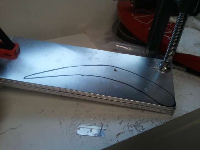
Attempting to cut all the ribs at one time (unsuccessfully)
While this was going on in my garage, I was also planning the wing uprights. The biggest challenge here was fastening the uprights to the trunk lid. I wanted the uprights to be as far outboard as possible, but the space inside the car to secure the fasteners was limited. The uprights eventually ended up mounted 38” apart. But The Wing had a span of 44”. In a metal working shop, a tool called a “Brake” would be used to make precision bends in the aluminum. The brake we have is nowhere near capable of bending 1/8” aluminum so an alternate method was required. Several methods failed before a solution was discovered. The method that worked went as follows:
1) Place a 12” long
chunk of wooden 4”X6” on the garage floor.
2) Place aluminum upright on wood block.
3) Place second piece of 4”X6” on top of aluminum.
4) Carefully align the desired line of bend with edges of wooden blocks.
4) Carefully align the desired line of bend with edges of wooden blocks.
5) Kneel on top wooden block.
6) Bash aluminum with 15Lb anvil until desired shape is
achieved. This process took hours (instead of the minutes it would have taken with the correct tools) and required some fine tuning (bashing) with a brass mallet, but the desired bends were achieved and the scars were quickly painted over.
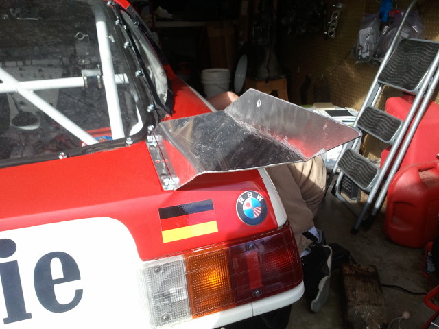
Wing Upright in place
Meanwhile, the lack of proper tools was causing the building
of The Wing to take much longer also. I
needed 72 brackets cut from a piece of L shaped aluminum. This would have been easy work with a bandsaw,
but the job was very slow going using only a hacksaw. 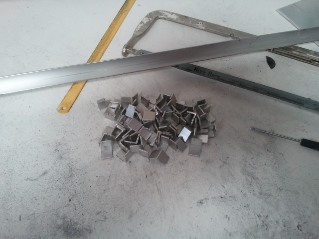
Pile of (72) Brackets
Once these were cut, each was matched with a specific location on a rib and marked, and then drilled using the high precision tools available in my garage.

Speedchimp Racing precision drilling station
After the brackets had all been drilled, they were matched
up with each rib and riveted into place.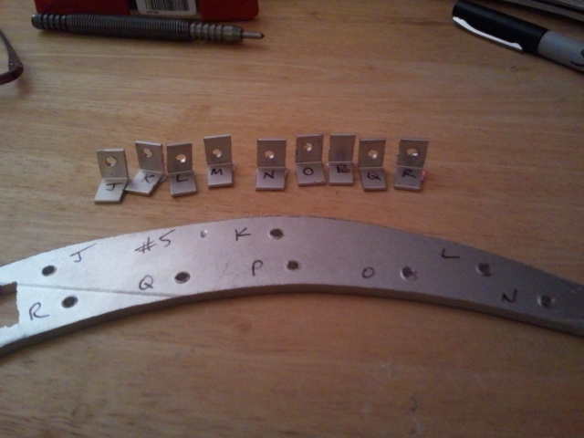

Rib #5 with custom brackets and completed rib assemblies
The ribs were then JB Welded to a ½” square steel tube. The steel tube would serve two purposes; strengthen The Wing and allow a threaded steel rod to pass through the middle of the wing to tie the two uprights together. An additional aluminum bar was JB Welded into place on the lower side trailing edge of the wing to keep the ribs parallel and to provide an anchor point for the skin of the wing when I began riveting it in place.

Letting the JB Weld cure
After allowing the JB Weld to cure, I began putting the skin into place. I won’t go into the details, but my first attempt at skinning The Wing was a catastrophe. The second attempt at skinning The Wing went much better and was almost completely free of drama or significant problems.
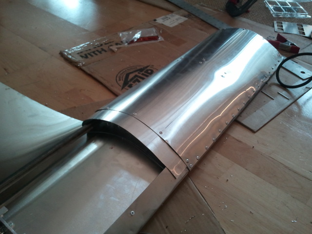
The skin going on The Wing
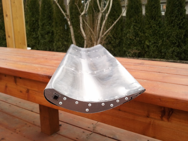
Skin in place
With the skin in place, the last step of construction was to
build end plates. I originally was going
to build these out of aluminum, but I didn’t like the thickness or strength of
any of the aluminum that I had in the garage.
I decided to use a piece of steel that I had lying around. Designing the end plates consisted of; 1)
tracing the outline of airfoil shape on a piece of graph paper, 2) determining
the imaginary line running through the airfoil that equaled a zero degree angle
of attack, 3) finding the imaginary line that equaled a 13 degree angle of
attack (this was determined to be the angle at which The Wing would generate
the most downforce), and 4) drawing the outline of an endplate that looked
decent. Once the design work was done,
the shapes were cut out of the steel plate and riveted to the ends of the wing.
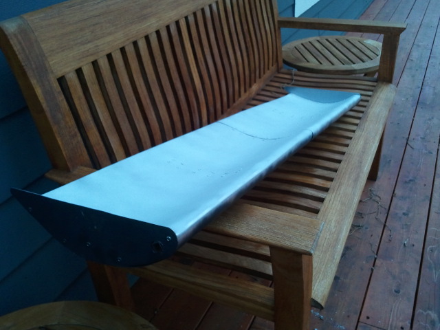
End plates in place and bare metal coated with primer
Part 3 - The Air Dam
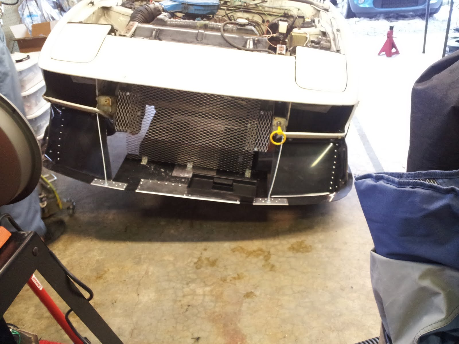
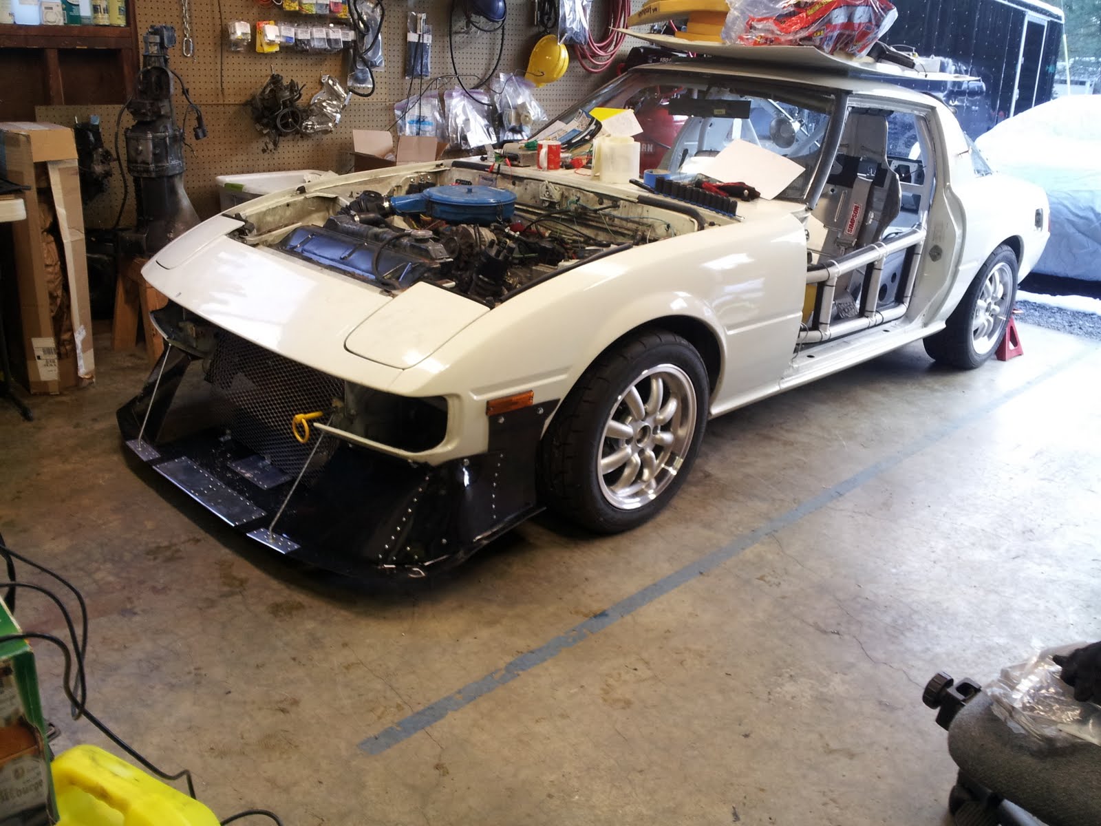
The Air Dam is the bit of fabrication that had me the most
concerned. By its very nature, The Air
Dam was going to be subject to aerodynamic forces and occasionally dragging on
the ground and thus would need to have good inherent strength. Design and fabrication was also going to be
difficult because of the shape of the front of the car. In short, I really was not looking forward to
this part of the build because I had very little confidence that this would
turn out decent at all and I really had no idea how to accomplish what I wanted.
Planning consisted primarily of looking at pictures of BMW M1s and thinking about how to shape and mount the thing. I briefly considered making The Air Dam from aluminum, but decided that ABS would be cheaper in the long run (because I expected to make many mistakes and be forced to start from scratch and ABS costs a lot less). We had been working on the car for months and I finally decided that the plans in my head weren’t going to execute themselves, so I broke out a tape measure and started estimating the amount of material I would need.
During planning, I couldn’t find a piece of ABS big enough
to make the entire thing out of one piece.
A minimum of two were going to be required. The ABS I selected came in
36”X36”X1/8” sheets. I decided to form
one half and see how it went. I drew
some rough lines on the piece of ABS and went after it with a scoring tool and
a heat gun.
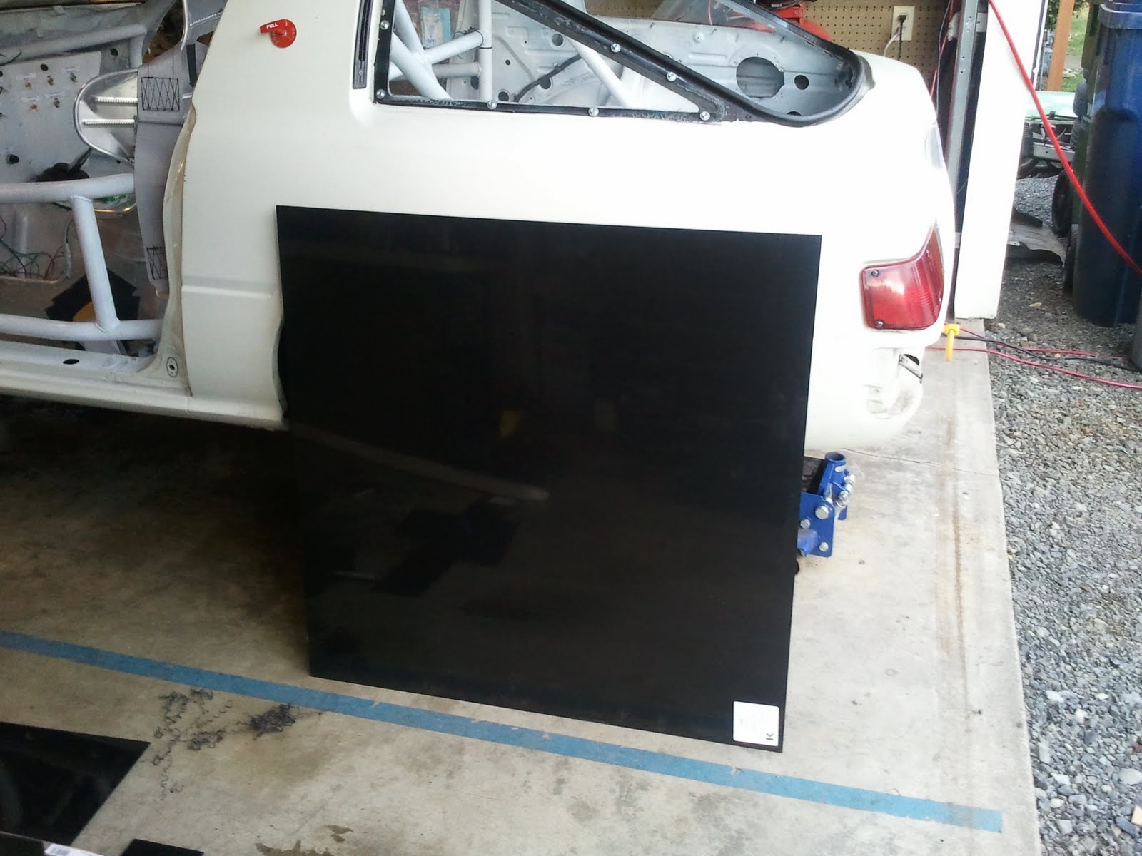
36” X 36” X 1/8” Sheet of ABS
I had an idea of how the thing should look and fit together with the car, but I struggled to get a design on paper. I was pretty sure that this was going to be a complete failure…
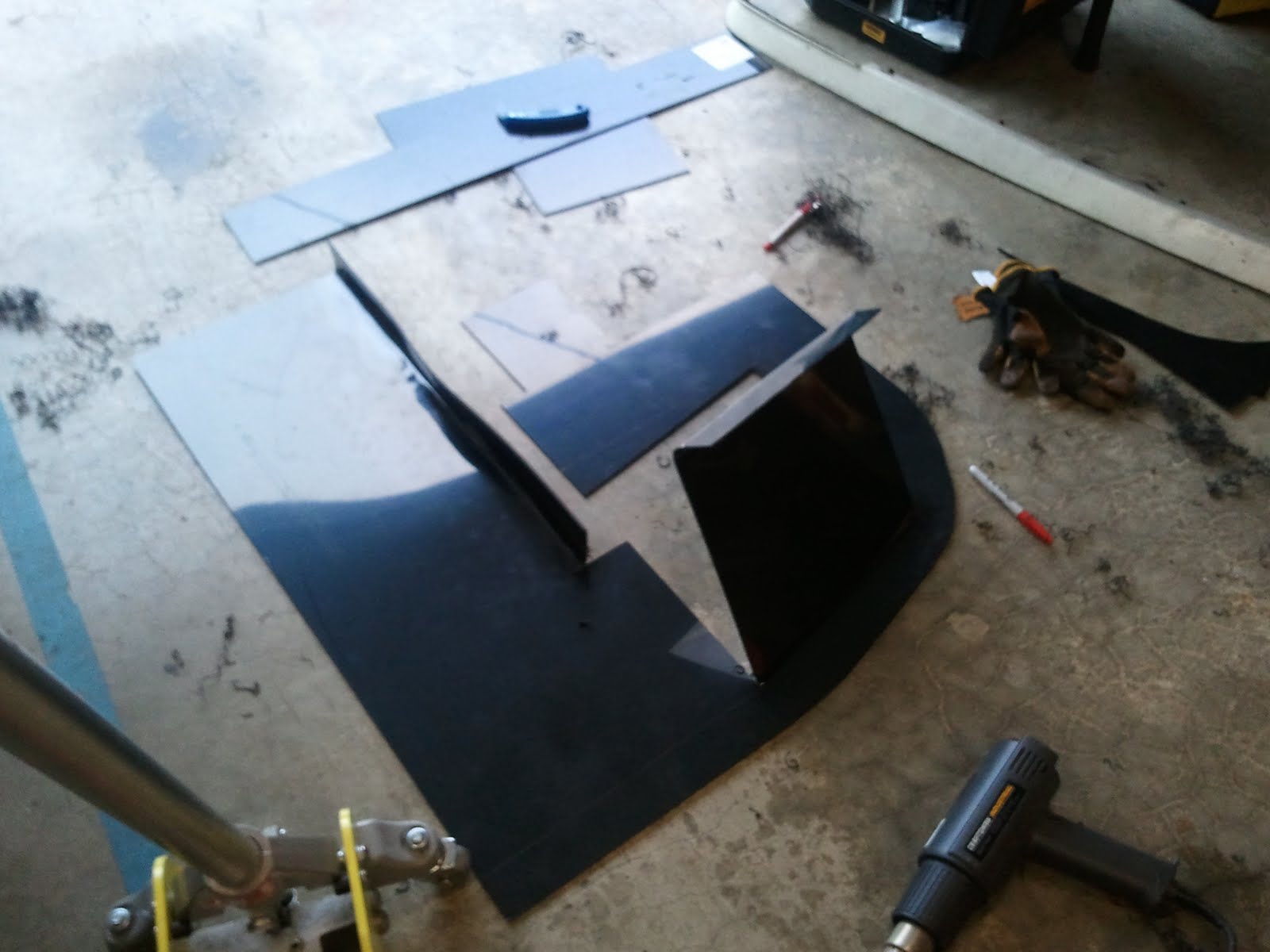
The first cuts and bends
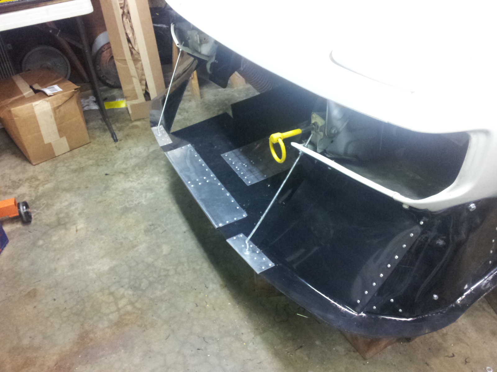
What happened next was pretty surprising. The pieces were fitting on the car the way I had envisioned. Sure, they weren’t perfect and no one would call the results “pretty”, but it was actually working!
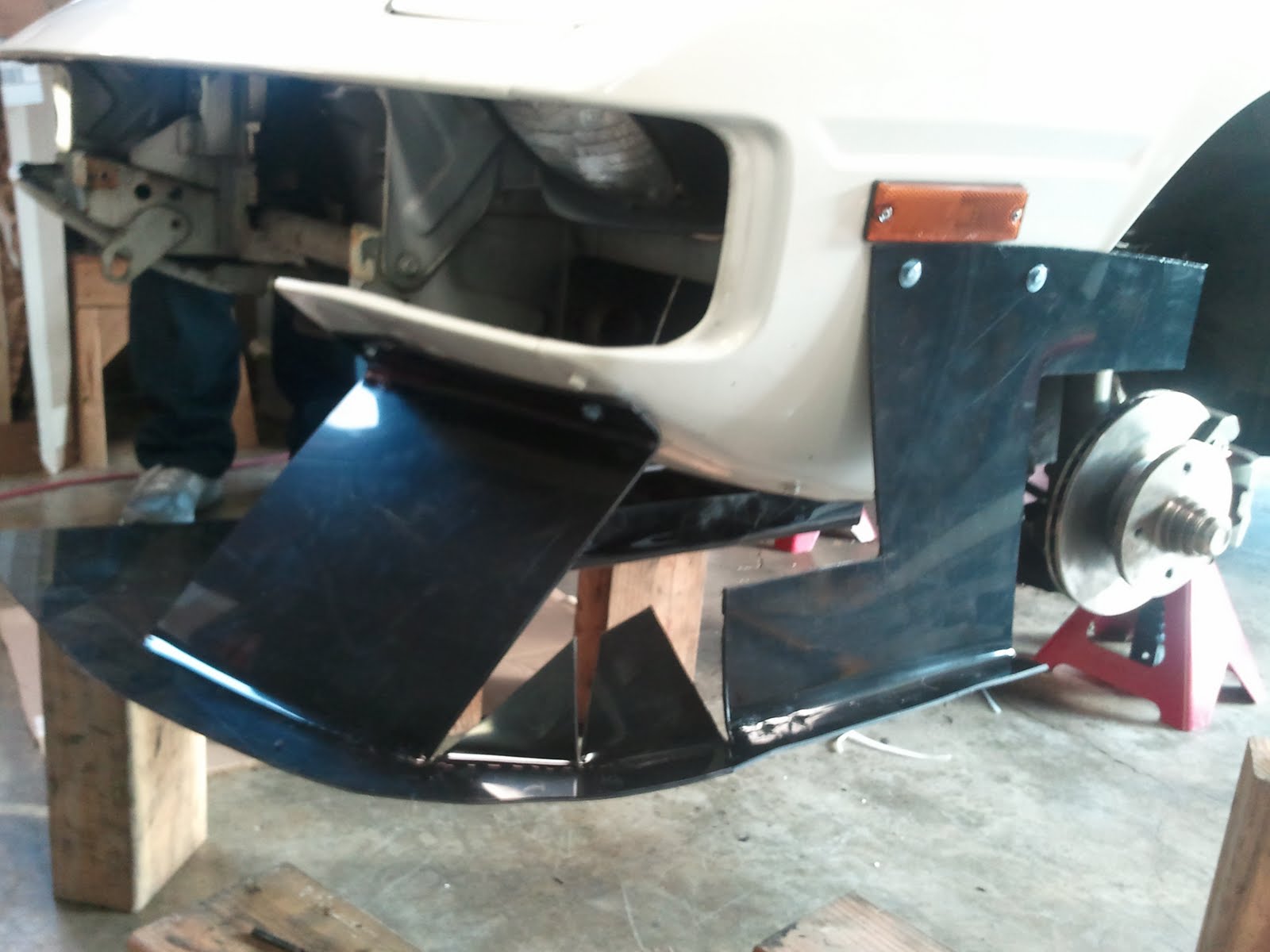
Test fitting the first half of The Air Dam
After getting the first half finished, the next trick was duplicating the effort to make a matching second piece. “Easy”, right? I was afraid of it being “too easy” and making a horrible mistake, so I really took my time to make sure that the cuts were all going in the right place (a mirrored shape of the first piece). It worked pretty well. The next step was to fasten the two pieces together. This was accomplished by sandwiching the plastic between sheets of aluminum then riveting the whole assembly together. The drilling and riveting was actually the most time consuming portion of the entire project. Approximately 80 rivets were used for fastening and strengthening The Air Dam.
When mounted on the car, it actually looked pretty
good. Not completely on center (I made
quite a few eyeball measurements and estimations during fabrication) and it
definitely has a homemade look, but a surprisingly cool result for a project
that I had been dreading and with amazingly few mistakes made and material wasted.
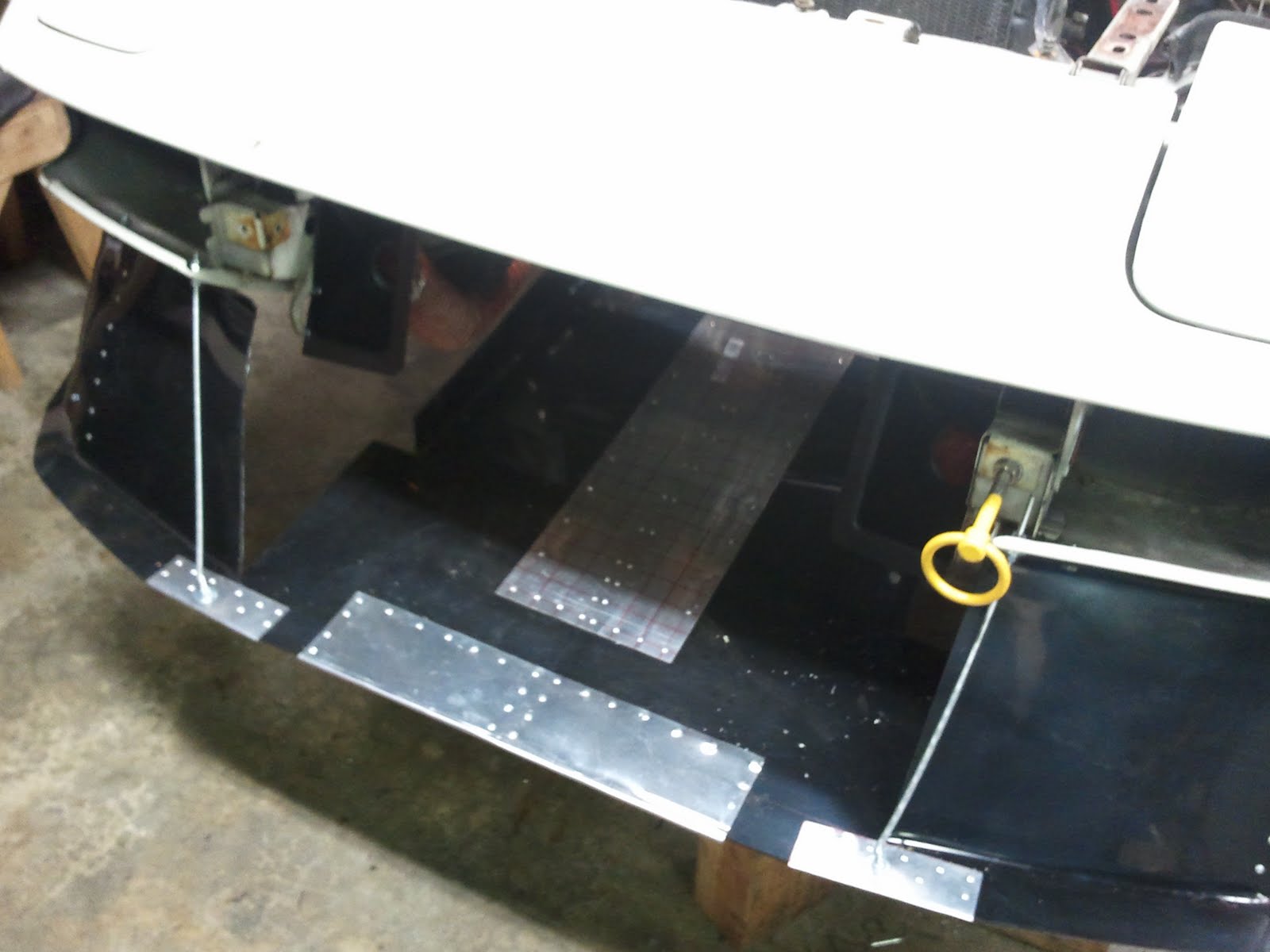
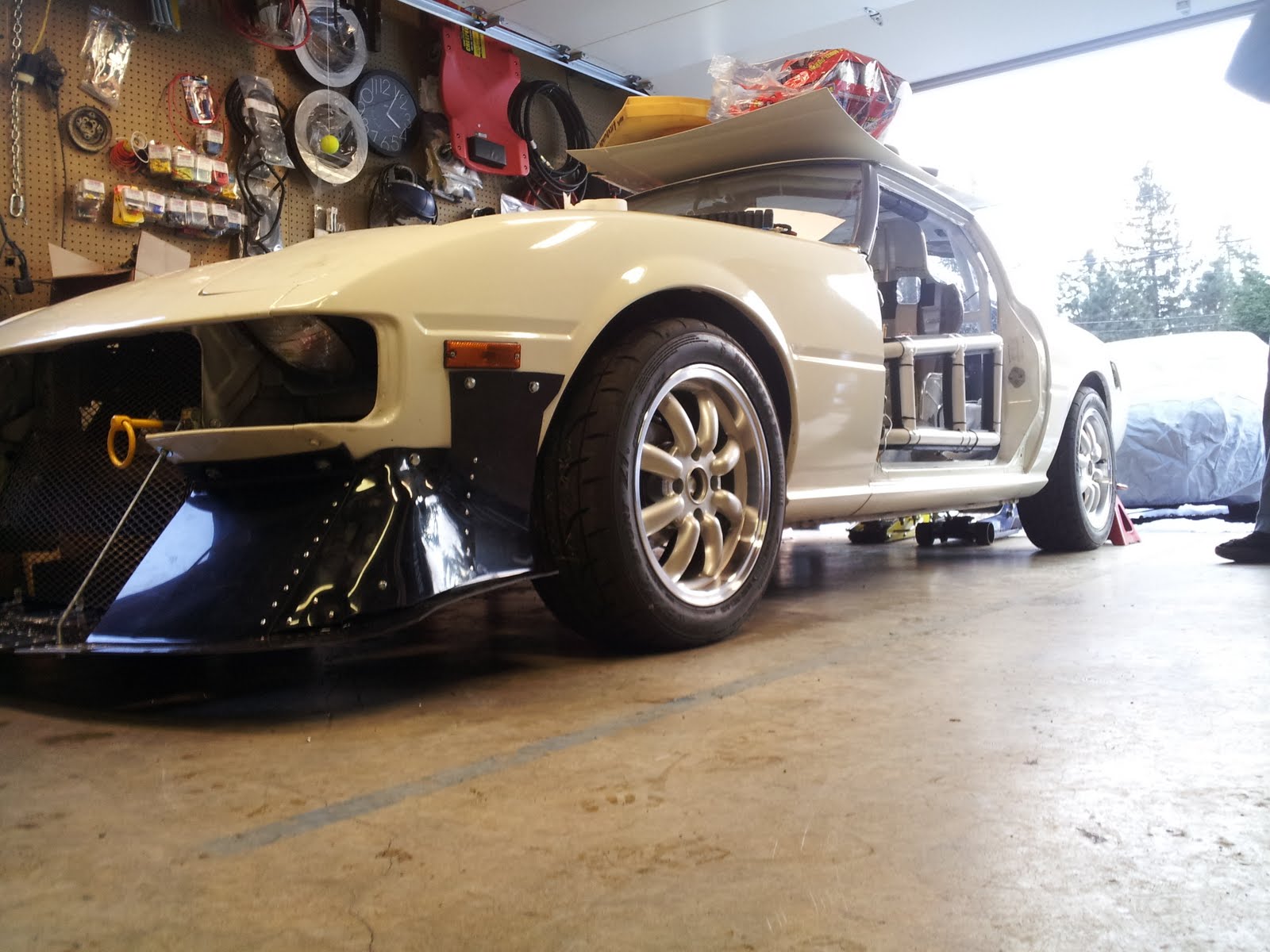
The finished Air Dam in place
Finishing touches included adding threaded rods to the
leading edge of the splitter (for both strength and adjustability) and JB
Welding nuts to the inside of the fenders so that The Air Dam could be removed
without completely disassembling what was to come next…
Part 4 - The Grill
This was another project that I was dreading, primarily
because I only had a very vague idea of how to do it. I already had ABS that I had originally purchased
for the Air Dam but decided not to use because the sheets were only 24” X 12”
and ¼” thick. Due to the size of the
opening in the front of the car, I was going to have to use 3 sheets somehow
fastened together.
Melissa had been eager to help with the car so she was
tasked with fabricating a prototype out of cardboard. She finished the job in record time and it
was perfect. Unfortunately I didn’t take
any pictures of her pattern, but the pictures of The Grill that follow are
exact duplicates of the pattern she created, so obviously, she nailed it.
The first steps went quickly; layout ABS pieces & tape
them together. Tape Melissa’s pattern to
the plastic and trace an outline. Use a
straight edge to clean up lines and ensure that measurements are consistent
between both sides. Use a drill and step
bit to cut radii into corners, use a jigsaw to make straight line cuts.
I knew that heating and bending plastic this thick was going
to be a challenge, so the pieces that needed big adjustments were placed into
the oven to heat soak. Then we used a
heat gun to soften the plastic where the bends needed to be.
While I was cutting the plastic, Carl was cutting and
painting expanded steel mesh that would fasten the three pieces together and
provide the same sort of vents as the real M1.
Next came the actual assembly. Drilling holes and popping rivets.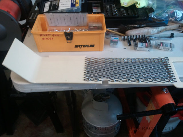
Assembling the driver’s side and center section (note the notch cut to
clear the tow hook)
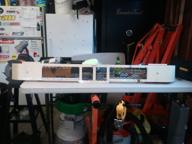
The finished Grill
The final part of assembly was figuring out how to mount the
grill to the car. This turned out to be
pretty easy. Fasteners at each end and
three custom fabricated brackets in the middle were enough to robustly install
the thing.
Part 5 - The Paint
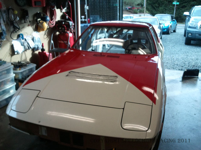
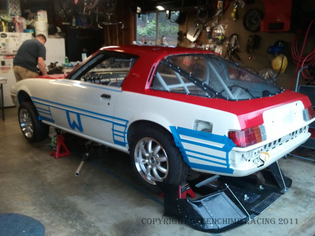
As I had mentioned, the original plan was to paint the car in classic BMW M1 Procar (a mid-‘80s BMW M1 specific racing series) colors; tri-color stripes on a white field.
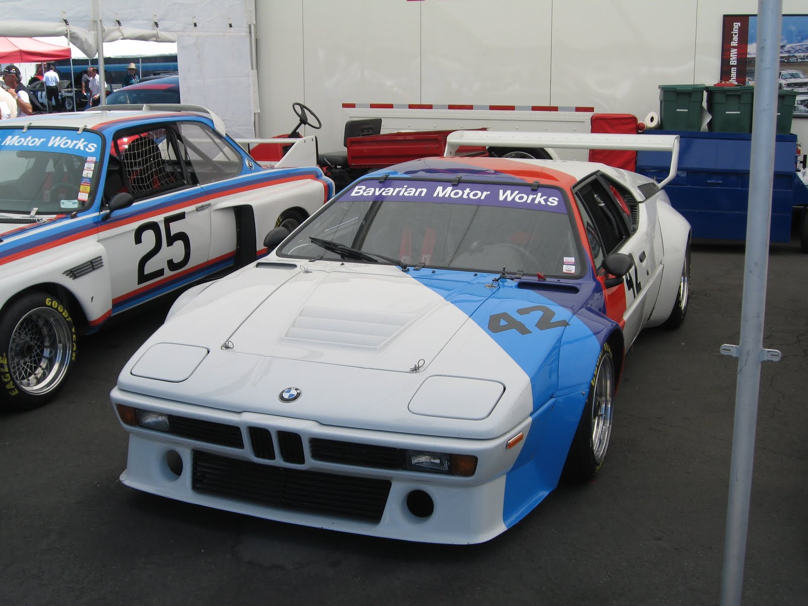
Plan A (it looked so easy!)
Our plan had a lot going for it. With the car already white, the paint job
would be relatively easy and the car was going to be instantly recognizable to
anybody that knew anything about BMW “Works” colors. It was the “recognizable” factor that turned
out to be a problem. By this point in
time we had been doing LeMons research for quite a while and one of the things
that our research turned up was that the paint scheme we planned to do had been
already been done. Not just once, but
quite a few times, including two cars at the same race with this paint scheme. Our stunningly original and clever idea was a
dud. After a lot more surfing the
intertubes and discarding a few other ideas for paint schemes, we decided to go
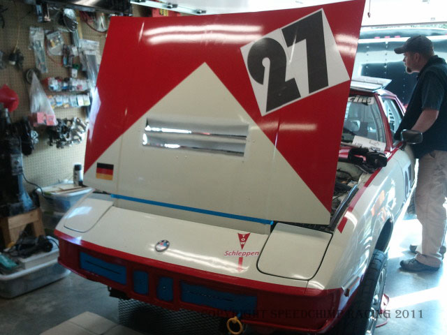
with classic Marlboro livery which had been used by a couple different BMW M1s. We didn’t want it to actually say “Marlboro”
though (R.J. Reynolds wasn’t actually sponsoring us, why advertise for them?),
so the search was on for a Marlboro parody.
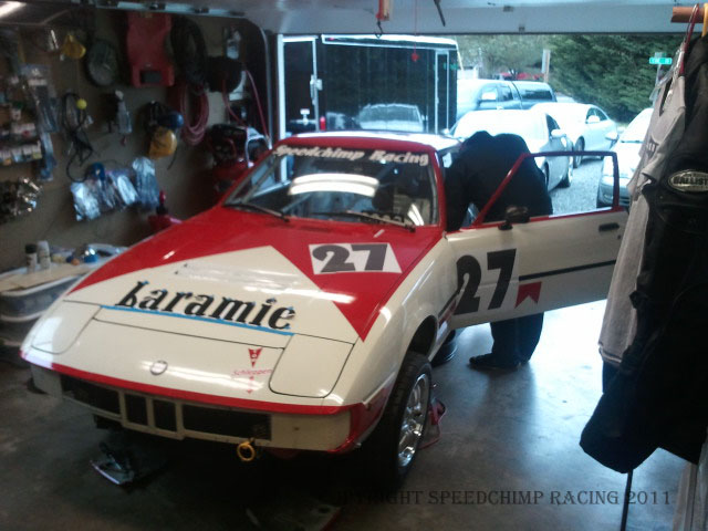
We finally settled on Laramie (an actual cigarette brand that went out
of business in the ‘50s). Laramie is a
brand of cigarettes satirized on The Simpsons.
Sure, the idea wasn’t particularly original (or our own), but we were
beginning to feel a time crunch.
Plan B
Painting was relatively easy. Find a few decent pictures of the real
car. Tape things off and apply paint
with rollers and brushes.The results are stunning and speak for themselves…